Our services

Thermovision

Thermovision Measurement Laboratory operates as part of accredited Testing Laboratory. In the scope of accreditation the Laboratory performs temperature distribution measurements of electrical equipment of all voltage levels.
termogram odłącznika 110kV

Accredited activity of the Laboratory is determined in The Scope of Accreditation of the Testing Laboratory no. AB 269, that is available at any request of the Customer (available also on PCA website – www.pca.gov.pl.


In the scope of accreditation the following measurements are carried out:

  • thermovision measurements of the main current path elements at high, medium and low voltage substations as well as at overhead lines,
  • thermovision measurements of power transformers,
  • thermovision measurements of generators,
  • thermovision measurements of temperature distribution on the surface of thermal insulation jacket of power boilers, turbines as well as process and district heating pipings,
  • thermovision inspection of patency of the power boilers' furnace cooling tubes.

In addition, the scope of activity includes:

  • diagnostic testing of equipment and plants, among other things: motors, boilers, flue gas ducts, electrofilters, chimneys, etc., made on the basis of temperature distribution on a surface during normal operation,
  • temperature distribution tests on a surface of building partitions and analysis of exaggerated losses of warmth in the construction,
  • comprehensive tests of the building outside coatings' thermal characteristics and evaluation of the technical condition of different installations at industry plants, shopping centres, etc.,
  • inspection of air-tightness of the underground heat distribution network and evaluation of the technical condition of the underground heating piping on the basis of temperature distribution analysis on a surface of the ground covering the piping.

During more than 30 years of activity we have performed tests and thermovision measurements of electrical power equipment at all power plants and HV substations as well as at many industry plants in the entire country.

We have been implementing thermovision diagnostic testing in domestic power industry, developing, among other things, temperature evaluation criteria of the current connections at substations and power transmission lines. 
We introduced the aeronautical technique used for thermovision inspection of overhead power lines and drawn up the method of monitoring the patency of boiler pipes.

Thermovision Measurement Laboratory carries out tests with the thermovision equipment type ThermaCAM P60.
The equipment specification is presented below:

  • range of the temperature measurement: from -40°C to 2000°C,
  • field of view depending on the applied lens: 12° x 9° or 24° x 18°,
  • geometrical resolution: 0,6 mrad (lens 12°) or 1,3 mrad (lens 24°),
  • range of spectral sensitivity: 7,5 – 13 mm.
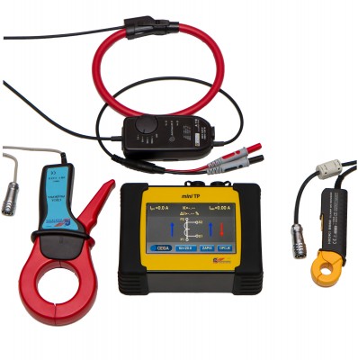
miniTP-ty
miniTP-pomiary
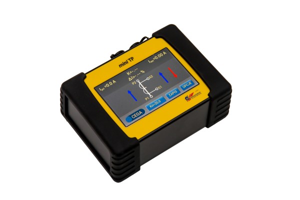
miniTP---prawy
miniTP---osprzt
miniTP---lewy
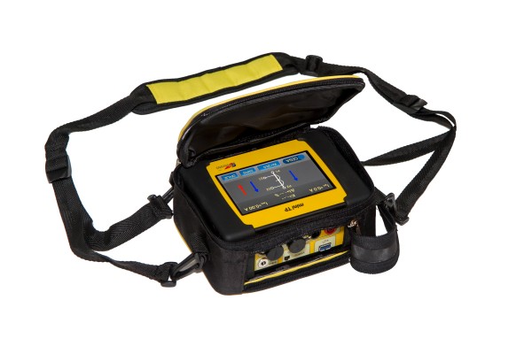
miniTP---futera
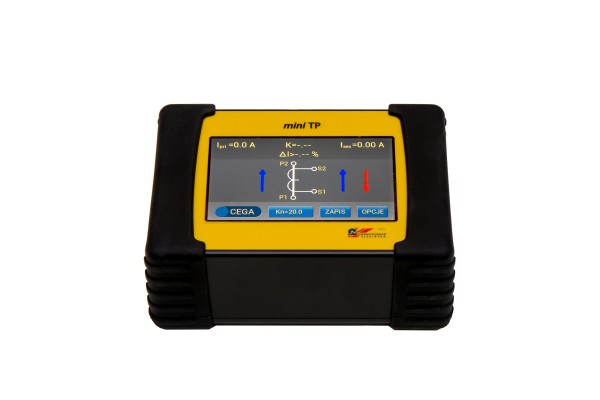
miniTP---front

All questions should be directed to:

  • Krzysztof Patschek, This email address is being protected from spambots. You need JavaScript enabled to view it., 32 237 66 49, 691 856 350.
 

Adjustment - service - of the measuring equipment

PERIODIC INSPECTIONS, ADJUSTMENT, CALIBRATION, REPAIRS We carry out adjustment and service of measurement equipment, which is the main scope of our company’s activity.

The Team started to perform that kind of works many years ago in a different organizational structure. 
Continuing this activity in new conditions the Team is continuously adapting the scope of activity to the current needs of Customers as well as to the requirements of management systems that are being introduced. Cooperation with the Measurement Equipment Laboratory guarantees the comprehensiveness of our services. The Laboratory operating in the scope of accreditation offers calibration of measurement equipment (according to the PN-EN ISO/IEC 17025:2005 standard) and for the purpose of metrological confirmation of the measurement equipment, the offer common with the Laboratory includes adjustment, calibration and inspection (verification) of selected characteristics of the apparatus tested, basing on the scope of tests agreed with the Customer and in accordance with the requirements of the PN-EN ISO 10012:2004standard and the ILAC-G8:03/2009 document.

All questions should be directed to:

  • Adam Stokłosa, This email address is being protected from spambots. You need JavaScript enabled to view it., tel. 32 237 66 62,
  • mgr inż. Michał Pniewski, This email address is being protected from spambots. You need JavaScript enabled to view it., tel.32 237 66 63.


Inspection of energy metering/billing setups

The scope of energy metering systems inspection includes:

  1. Visual inspection of the outside state of current and voltage transformers enclosures.
  2. Check out of fastening of current and voltage transformers.
  3. Check out of certificate from Central Office of Measures (Główny Urząd Miar) approved types of transformers.
  4. Check out of the state of the energy supplier's leaden seals put on:
    • meter boards,
    • Ska terminal strips,
    • covers of meter's terminal strips,
    • covers of the current and voltage transformer's terminal strips,
    • doors of metering chambers,
    • disconnector of the voltage measurement bay.
  5. Check out of the current circuits scheme of connection:
    • state and correctness of primary connections of current transformers,
    • state and correctness of the current transformers' secondary windings connections to Ska terminal strip,
    • state and correctness of the Ska terminal strip circuits and connections between Ska terminal strip and energy meters' terminal strip.
  6. Check out of the voltage circuits scheme of connection:
    • state and correctness of primary connections of voltage transformers,
    • state and correctness of the voltage transformers' secondary windings connections to Ska terminal strip,
    • state and correctness of the Ska terminal strip circuits and connections between Ska terminal strip and energy meters' terminal strip.
  7. Check out of the load of current transformers' secondary windings and voltage transformers' secondary windings as well as certifying the transformers conformity (or lack of conformity) to the PN-E -04700 standard.
  8. Check out of the current and voltage transformers' ratings (rating plate) against the actual state of the transformers.
  9. Measurement of the resistance of current and voltage transformers circuits.
  10. Check out of the accuracy of current transformers for the burden of cores 5%, 20%, 100% and 120% of rated current, under active load as well as for the burden of 25% and 100% of the transformer rated load.
  11. Check out of the accuracy of voltage transformers for the value of 80%, 100% and 120% of rated voltage, under active load as well as for the value of 25% and 100% of the transformer rated load.

We carry out the measurements with the measuring instruments that are in cohesion with the national measurement standards.

The measuring instruments are calibrated by our Laboratory of Measuring Instruments accredited to the Polish Centre for Accreditation (PCA).


All questions should be directed to:

  • mgr inż. Paweł Polus, This email address is being protected from spambots. You need JavaScript enabled to view it., 32 237 66 53
  • inż. Jerzy Wrzosek, This email address is being protected from spambots. You need JavaScript enabled to view it., 32 237 66 02

Testing of the energy quality

The scope of tests encompasses all quantities being characteristic of quality of the energy detailed at the up-to-date regulations, such as:

  • level, frequency and changes of supply voltage root-mean-square value,
  • voltage and current higher harmonics contents (determining of voltage and current distortion factor),
  • voltage asymmetry (in three-phase systems),
  • energy supply interruptions,
  • quick-variable changes of supply voltage (voltage dips and flares),
  • light flickering noxiousness (due to voltage fluctuations, so-called flicker effect), that is subjective impression of the change of illuminance.

Moreover, we offer:

  • monitoring of the active and reactive power consumption as well as the power flow in any time intervals,
  • technical consulting on establishing the terms of power supply,
  • selection, installation, start-up and check measurements of the equipment for the reactive power compensation,
  • selection of equipment to ensure the correct operation of energy receivers.

The measurements that are the basis for energy quality analysis, are carried out with the recording equipment with up-to-date verification certificates. The results of our works can serve as credible evidence in controversial issues on the line supplier – consumer of the energy. In view of the necessity of permanent control of energy quality, we offer our customers systems realized in our company for continuous monitoring of the power network parameters. The systems allow measurement of electric power quality at the selected points of the power network as well as transmission of data to the central computer. Power quality monitoring system consists of distributed Power Network Analysers (AS). Every AS is an independent measuring point. The AS internal memory allows to record and review the selected parameters and events.RS485/232 interfaces and Modbus protocol is used for communication between analysers. Depending on the noise and distance, the transmission paths can be of fibre-optic, electric twisted-pair cable or wireless systems (GPS, radio link). All over one GPZ (Main Supply Point) can operate simultaneously up to 64 AS. The individual AS, apart from energy quality parameters, measures and records the following power network parameters:

  • V, I, KW, KVR, KVA, cos, tg, Ekv, Ekvr, Ekva
  • real-time diagrams of current and voltage (storage oscilloscope).

Power network parameters' quality monitoring system provides:

  • communication with Power Network Analysers (AS),
  • on-line visualization of quantities measured,
  • alarm signalization on exceed the thresholds and limits,
  • archiving and off-line browsing of quantities measured,
  • web access to the quantities measured,
  • processing of quantities measured,
  • recording to a file / printing the archived data,
  • co-operation with other systems operated in power industry.

We guarantee a liable and diligent realization of works ordered.

All questions should be directed to:

  • inż. Jerzy Wrzosek, This email address is being protected from spambots. You need JavaScript enabled to view it., 32 237 66 02
  • mgr inż. Adam Kurzyński, This email address is being protected from spambots. You need JavaScript enabled to view it., 32 237 66 54
  • mgr inż. Paweł Polus, This email address is being protected from spambots. You need JavaScript enabled to view it., 32 237 66 53

Noise and Vibration

We offer services in the scope:

  • making out the assessment of influence of the device and system noise on the environment on all stages of the investment process,
  • making out the proposal for the issue of the permit for noise emission to the environment under the Act of Environmental Law item 6. Journal of Laws no. 62 from 27 April 2001,
  • guarantee measurements of system noise,
  • measurement and analysis of the devices noise, working out the conception and project as well as implementing the protection system to limit noise emission,
  • consulting in the scope of noise at the stage of preparing the contract for the purchase or the assembly of installation,
  • measurements and evaluation of the noise and vibration.

We have modern measurement equipment and computer software.

During the tests we use the newest measurement system - multianalyser type 3560 PULSE of Bruel & Kjaer co. for the measurement and analysis of sound and vibration.

We deal with all small and big objects, such as:  transformers and hydro installations in residential buildings, ventilators and climatizer installations, pump house, high voltage lines and transformer stations, power plants and other industrial plants.

All questions should be directed to:
  • inż. Ireneusz Malciak, This email address is being protected from spambots. You need JavaScript enabled to view it., 32 237 66 39,
  • Marek Pawlik, This email address is being protected from spambots. You need JavaScript enabled to view it., 32 237 66 38.


Calibration of the high voltage measuring and testing equipment

We perform services in the scope of calibration of the high voltage measuring and testing equipment for the following instruments and devices:

  • kilo-voltmeters,
  • oil testing devices (e.g. ABO, PGO),
  • cables testing devices (e. g. ABK),
  • testing stations.

Regular use of our services gives the user of the voltage measuring and testing equipment the possibility to confirm the safety and credibility of high voltage measurements carried out as part of the current operating works. Long-standing experience gained while providing service in this field allowed the Laboratory staff to reach a high level of specialization, particularly in the scope of calibration of the high voltage measuring equipment (for example in the localization of cable damage) installed in measuring cars and in the scope of static electricity measurements. We have the measuring equipment that keeps a measurement traceability with the National measurement standards assuring the possibility of calibration in the following ranges:

  • 200 kV (AC/DC),
  • 400 kV (DC).

We perform works in places indicated by the Employer, and in justified situations we expect the user of the serviced item to deliver it to the Laboratory registered office.  Currently we have the scope of accreditation of the Measurement Equipment Laboratory - AP 063 that allows us to calibrate the high voltage measuring and testing equipment in the range to 100 kV AC.

All questions should be directed to:

  • mgr inż. Tomasz Guzy, This email address is being protected from spambots. You need JavaScript enabled to view it., tel. 32 237 66 60,
  • inż. Jerzy Zmysło, This email address is being protected from spambots. You need JavaScript enabled to view it., tel. 32 237 66 63.

Computer system for visual presentation and registration of synchronization process criteria quantities and power system switching

Computer system for visual presentation and registration of synchronization process criteria quantities and power system switching

The system presented here is a result of our long-term experience in the scope of registration and analysis of electric processes and it is an answer  to the growing demand of the market resulting from the necessity of executing international synchronization processes and switching of separated island systems to the NPS (National Power System) (e.g. power network of large industrial plants). The virtual measurement environment has been organized that, from the user point of view, consists of conventional connected with one another instruments graphically presented on a computer screen.

The system is characterized by significant flexibility that cannot be achieved with conventional technology. On the basis of PSE-Operator S.A. decision the MUW system was adopted for applying in cross-border electricity exchange transformer stations and was installed in the following transformer stations: Mikułowa, Krajnik, Krosno-Iskrzynia, Mory and Wrocław heat and power plant. The system played the substantial role during tests of connection of UCPTE and CENTREL systems in October 1995. Starting next installations in transformer stations is planned e.g.: Bujaków, Wielopole.

MUW devices found application during the entire sequence of system trials in separating, creating and repeated synchronization of the island systems to the NPS (National Power System).  An example constitute the island operation tests carried out at the power plants: Połaniec (1995, 1996), Skawina (1996, 1997), Turów (1999, 2000, 2004).

The system is offered in the industrial workmanship based on modern elements of reputable producers. MUW provides all functions of traditional synchronizing units and introduces new functions impossible to obtain with old technologies. Metrological properties of the MUW device are particularly significant.

The fact that the system doesn't require applying any additional computer devices is worth of stressing.

MUW system enables:

  • observation in the real time on the external industrial monitor of criteria parameters of switching processes (slipping, voltages difference, phase shift and the like),
  • registration of criteria parameters of switching processes,
  • assembly in the automatic system cabinet of 19" standard.

Experience gained from the previous operation of the MUW system showed that synchronization of large power systems and island systems carried out with the use of conventional technical methods was unusually difficult and to all intents and purposes impossible to realize. A possibility of registration and documenting the whole switching process is an additional advantage resulting from application of the MUW system. As an option the system can be equipped with the recorder of transient states (current surges, power swing, etc.) appearing in the moment of closing of circuit breaker.  High-tech solutions both in the equipment as well as the software were applied for the design of the proposed system. Visual presentation and registration system of the MUW can be consolidated with the wide range of automatic and semi-automatic synchronizers of domestic and foreign production. Our company can also undertake the realization of the complete synchronization system containing among other things the automatic switching system cabinet. The above works were successfully carried out by Energopomiar-Elektryka company at the majority of customers of the MUW system. During the 10th jubilee fair "The high technology for Power Industry" at Bielsko-Biała 1997 PSE-Operator S.A. granted our Computer disturbance registration system, control device state signalling system and switching processes visualisation system a gold medal.


All questions should be directed to:

  • mgr inż. Grzegorz Grzegorzyca, This email address is being protected from spambots. You need JavaScript enabled to view it., 32 237 66 42

Electrical parameters registration and analysis system SAS-PLUS

The presented system is a result of our more than 20 years of experience in the scope of registration and analysis of electrical quantities which is meant to meet the market needs connected with the necessity of performing sophisticated analysis of power network at large industry plants, in accordance with the domestic standards (e.g. determination of energy quality parameters acc. to the PN-EN 50160 standard).

A virtual measurement environment has been designed which, from the user's point of view, consists of conventional, interrelated between one another measuring instruments graphically presented on a computer screen. Moreover, its software has a great flexibility.

The system is offered in the industrial workmanship (industrial computers and measurement cards, real time operating systems, mechanics of 19" standard) based on modern elements of reputable producers.

The SAS-PLUS provides all functions of conventional measuring devices as well as introduces new functions which cannot be used with the old technology.

Particularly significant and distinguishing feature of the SAS-PLUS system are metrological properties guaranteeing measurements of above average accuracies and dynamics in the time domain. SAS-PLUS

The SAS-PLUS system has the metrological confirmation issued by the specialist measurement equipment laboratory accredited by the Polish Centre for Accreditation (PCA).

Measuring signals delivered to the system:

  • voltage from voltage transformers of the tested supervised system (UL1, UL2, UL3, U0),
  • currents from current transformers of the supervised system (IL1, IL2, IL3, I0),
  • binary signals.

SAS-PLUS system allows:

  • local (on the monitor connected) and remote (at the selected workstations operating in heterogeneous distributed computer network) measurement and visualization of the selected electrical parameters of the system tested (rms currents and voltages, harmonic content in currents and voltages, t.h.d. coefficients, active and reactive power, electric energy, frequency, phase shifts, voltage unbalance coefficients, power direction of flow, exceeding of assumed limits e.g. power, etc.). These tasks are being performed in the real time in order to determine the current and historical state of the supervised electric power systems,
  • local and remote registration of selected electrical parameters,
  • registration of disturbances (dynamic electrical transient states and quasi-steady states),
  • registration of events.

SAS-PLUS system cooperates among other things with Power System Protection. The system is characterized by high-tech solutions both in the equipment as well as the software. The device constitutes the element of the distributed heterogeneous measuring network of the real time.
System of the visualisation and the registration SAS-PLUS can be consolidated among other things with:

  • any class supervision system working under the computer operating system selected by the Customer: MS Windows, LINUX or UNIX using open network communication protocols for manufacturing application,
  • WWW browsers of the selected SAS-PLUS Customers,
  • telecommunication systems.

Experience gained at the current/previous operation of the SAS-PLUS system demonstrated that comprehensive analysis of large power networks performed with the use of conventional technical methods was unusually difficult and to all intents and purposes impossible to realize. A possibility of registration and documenting the whole process is an additional advantage resulting from application of the SAS-PLUS system. The system is equipped with the high class recorder of transient states (current surges, power swing, etc.) and event recorder.  ZPBE Energopomiar-Elektryka company can also undertake the realization of the complete system containing among other things the automatic switching system cabinet and computer-based telecommunication device. The above works were successfully carried out by ZPBE Energopomiar-Elektryka company at the majority of Customers. The basic specification of SAS-PLUS system Measurement circuits:

  • set of three-phase voltage inputs with/from optical isolation, rated voltage Un: 100/√2 V, operation range: 0 V to 200 V,
  • set of three-phase current inputs with/from optical isolation, rated current In: 1A, operation range: 0A to 10A,
  • rated frequency fn: 50 Hz,
  • frequency operation range: 45…65 Hz,

Auxiliary voltage:

  • SAS-PLUS system auxiliary supply: 230V AC from the substation UPS system (uninterrupted power supply).

Binary input/output:

  • the device is equipped with 16 programmable insulated binary input/outputs for connection to external secondary circuits.

Errors:

SAS-PLUS system determines measured quantities of the following accuracy:

  • voltage and current rms values: class 0,1,
  • frequency: 0,001 Hz

All questions should be directed to:

Calibration of measuring equipment and instruments

We deal with the metrological service of a wide assortment of measuring equipment and instruments from basic analogue instruments, inductor type and similar ones to high-tech digital instruments measuring electric and nonelectric quantities (the temperature, the pressure and other physicochemical quantities in the reduced scope). We calibrate and check all these instruments (verify the results achieved with characteristics declared) for the purposes of metrological confirmation of the measuring equipment and instruments, under the label of a Trustworthy Laboratory - name in accordance with the contents of the PN-EN ISO 10012:2004 standard.

This part of the Laboratory activity also includes such works as: calibration of the high voltage measuring and testing equipment, calibration and modernization of the regulating and measuring system of thermal devices, measurements of static electricity and similar activities.

PCA

The calibration of measuring equipment and instruments used for the measurement of electric quantities is a prestigious direction of our activity and in this field we have the status of the accredited Calibrating Laboratory granted after meeting the requirements of the PN-EN ISO/IEC 17025:2005 standard.In the scope of accreditation we perform calibration of instruments for the measurement of AC, DC voltage, AC power, DC resistance and in case of digital multimeters we calibrate the capacity, frequencies and temperature measuring ranges. In addition we also carry out calibration of the high voltage measuring and testing equipment.

We perform works mainly in the registered office of our company, in appropriately prepared and adapted laboratory rooms. If necessary, we can also carry out works on the customer's premises, at the place of installation of the serviced item.

Owing to permanent cooperation of the Calibration Laboratory with the Measuring Equipment Team that is specialized in the scope of adjustment and servicing of the known assortment of measurement equipment, our services are really comprehensive.


All questions should be directed to:

  • Kierownik Laboratorium - mgr inż. Tomasz Guzy, This email address is being protected from spambots. You need JavaScript enabled to view it., tel. 32 237 66 60,
  • Kierownik ds. Jakości - inż. Tadeusz Wypych, This email address is being protected from spambots. You need JavaScript enabled to view it., tel. 32 237 66 66,
  • Kierownik Techniczny - inż. Jerzy Zmysło, This email address is being protected from spambots. You need JavaScript enabled to view it., tel. 32 237 66 63.


Wzorcowanie analizatorów jakości energii

Laboratorium Przyrządów Pomiarowych oferuje usługę wzorcowania mierników i analizatorów jakość energii. Usługa realizowana jest przy wykorzystaniu sygnałów testowych uwzględniających wytyczne szeregu norm: PN-EN 50160, PN-EN 62586, PN-EN 61000-4-30, PN-EN 61000-4-15, PN-EN 61000-4-7.

Diagnostyka zapobiegająca skutkom katastrofalnych awarii oraz anomaliom w systemie elektroenergetycznym

Diagnostyka zapobiegająca skutkom katastrofalnych awarii oraz anomaliom w systemie elektroenergetycznym z wykorzystaniem mobilnego zespołu szybkiego reagowania ma na celu rozpoznanie rozmiarów awarii, identyfikację jej przyczyn i ocenę jej skutków, wykonanie badań i pomiarów poawaryjnych urządzeń, określenie zakresu uszkodzeń i możliwości ich eliminacji, wprowadzenia, po naprawie lub ich wymianie na nowe, urządzeń do eksploatacji.

Dane kontaktowe

Zakład Pomiarowo-Badawczy Energetyki
"ENERGOPOMIAR-ELEKTRYKA"
Spółka z ograniczoną odpowiedzialnością
ul. Świętokrzyska 2, 44-100 Gliwice
woj. śląskie, Polska

(+48) 32 237 66 03 (sekretariat)

(+48) 32 237 66 15 (centrala)

(+48) 32 231 08 70 (fax)

Nasze wyróżnienia

gazela2010

gazela2009

gazela2008


UE ŚCP Europejskie Fundusze Strukturalne

UE Program Operacyjny Inteligentny Rozwój